


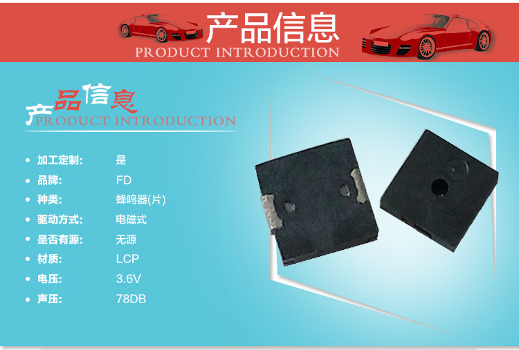
| 加工定制 | 是 | 货号 | SMD-050020F-03040N | 品牌 | 福鼎 |
| 型号 | SMD-050020F | 种类 | 蜂鸣器(片) | 驱动方式 | 电磁式 |
| 是否有源 | 无源 | 材质 | LCP | 规格尺寸 | 10*3.2(mm) |

买家须知:
1.所标价格为参考价,为节省时间,将同类产品同一标题列出,但价格并非统一,拍下前请联系卖家。(注:店内产品均不含税,可开普票,开票需加税金)。另有大量库存没有上传,如果您还没有查到您想要的型号,请与我们联系,我们可以为您研发制作偏冷门的电子元件!
2.电子元件是专业型的产品,技术含量较高,由于本身可能存在着多种品牌,后辍与封装,所以可能导致参数与性能的差异,有不慎,很有可能导致元件购买错误(此种失误,非质量问题一律不退换!),为了更好的解决您的问题,请您在购买我们元件前,将您所需产品的品牌、封装、脚位及后缀告诉我们!以便我们能准确迅速的发货。为了保障您的利益,切勿直接拍下并付款!!!
3.为避免运输过程中造成货物损坏或丢失给您带来损失,请您在收到货物时认真检查,如有问题请勿签收!时间与我取得联系,共同解决问题。勿在签收后提出数量不足,货不对板的情况,谢谢合作!
A. SCOPE
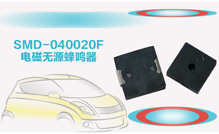
This specification applies magnetic buzzer, SMD-050020F-03040N
B. SPECIFICATION
| No. |
Item |
Unit |
Specification |
Condition |
|
1 |
Oscillation Frequency |
Hz |
4000 |
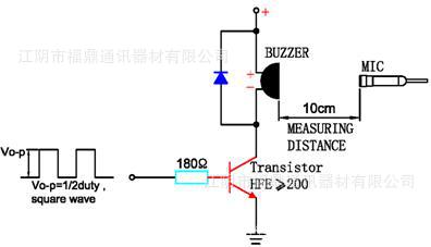
Vo-p=1/2duty , square wave |
|
2 |
Operating Voltage |
Vo-p |
2 ~ 4 |
|
|
3 |
Rated Voltage |
Vo-p |
3 |
|
|
4 |
Current Consumption |
mA |
MAX. 110 |
at Rated Voltage |
|
5 |
Sound Pressure Level |
dB |
MIN. 75 |
at 10cm at Rated Voltage |
|
6 |
Coil Resistance |
Ω |
12±3 |
|
|
7 |
Operating Temperature |
℃ |
-20 ~ +70 |
|
|
8 |
Storage Temperature |
℃ |
-30 ~ +80 |
|
|
9 |
Dimension |
mm |
5.0 x 5.0 x H2.0 |
See appearance drawing |
|
10 |
Weight (MAX) |
gram |
0.1 |
|
|
11 |
Housing Material |
|
LCP( Black ) |
|
|
12 |
Leading Pin |
|
Tin Plated Brass(Sn) |
See appearance drawing |
|
13 |
Environmental |
|
RoHS |
|
C. APPEARANCE DRAWING
Tol : ± 0.3 Unit: mm
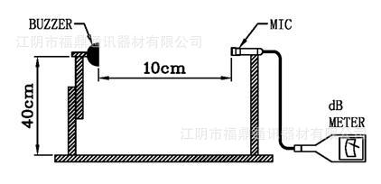
D.TESTING METHOD
Standard Measurement conditions
Temperature:25±2℃ Humidity:45-65%
Acoustic Characteristics:
The oscillation frequency, current consumption and sound pressure are measured by the
measuring instruments shown below
In the measuring test, buzzer is placed as follows:
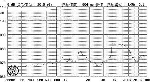
E. Typical Frequency Response Curve
F. Recommend Driving Circuit
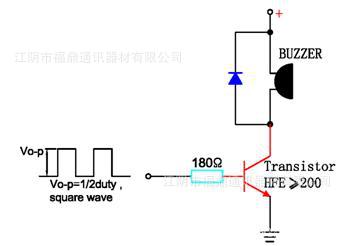
The base current Ib should high enough so that it saturates the collector current of the transistor with the CB load.
G. Soldering Condition
(1)Recommendable reflow soldering condition is as follows
(Reflow soldering is twice)
Note:It is requested that reflow soldering should be executed after heat of product goes down to normal.

Heat resistant line
(Used when heat resistant reliability test is performed)
(2)Manual soldering
Manual soldering temperature 350 ℃ within 5 sec.
H. RELIABILITY TEST
|
NO. |
ITEM |
TEST ConDITION AND REQUIREMENT |
|
1 |
High Temperature |
After being placed in a chamber with 80 |
|
2 |
Low Temperature |
After being Placed in a chamber with -30 |
|
3 |
Humidity Test |
After being Placed in a chamber with 90-95% R.H. at 40 |
|
4 |
Temperature Cycle |
The part shall be subjected to 5 cycles. One cycle shall be consist of: |
|
5 |
dro Test |
dro on a hard wood board of 4cm thick, any directions ,6 times, at the height of 75cm . |
|
6 |
Vibration Test |
After being applied vibration of amplitude of 1.5mm with 10 to 55 Hz band of vibration frequency to each of 3 perpendicular directions for 2 hours . |
|
7 |
Solderability |
Lead terminals are immersed in rosin for 5 seconds and then immersed in solder bath of +300 |
|
8 |
Terminal Strength |
The force of 9.8N(1.0kg) is applied to each terminal in axial direction for 10 seconds. |

TEST CONDITION.
Standard Test Condition : a) Temperature : +5 ~ +35℃ b) Humidity : 45-85% c) Pressure : 860-1060mbar
Judgment Test Condition : a) Temperature : +25 ± 2℃ b) Humidity : 60-70% c) Pressure : 860-1060mbar
I. PACKING STANDARD